Garbage Disposal Wiring Diagram
If your garbage disposal stopped working—or you’re replacing a unit—you’re probably staring at a wiring mess and hoping you don’t guess wrong. A garbage disposal wiring diagram helps you identify the correct hot, neutral, and ground connections and match the disposal’s wiring method to your circuit. Done correctly, the installation is straightforward; done incorrectly, it can create tripping, shock hazards, or a disposal that won’t start.
For more help, see our GE Garbage Disposal Installation: Removal, Wiring, and Setup guide.
Before You Wire the Disposal
Check the appliance label and manual
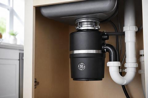
Start by reading the disposal’s data label and the installation instructions that came with the unit. Look for the listed voltage (typically 120V in North America), whether it supports plug-in or hardwired connections, and any special instructions for the ground and switch type. Record the model number exactly as printed—GE model numbers start with GFC for continuous-feed units (e.g., GFC520N, GFC1020N) and GFB for batch-feed units (e.g., GFB760N). Then follow the manual’s wiring diagram for the terminal layout and any approved connection method. This prevents you from wiring a terminal as if it’s supported when the manufacturer doesn’t allow it.
Confirm local code and circuit requirements
Before touching conductors, confirm the circuit type and protection requirements in your local electrical code. Many kitchens require GFCI protection for the branch circuit or for the receptacle feeding the disposal, but the exact requirement depends on your location and the way your circuit is set up. Also verify whether your home has a dedicated disposal circuit, what breaker size it uses, and whether neutrals are present in the junction box. If you’re missing a neutral where the setup calls for it, you can’t “make it work” safely—stop and get clarification from a licensed electrician.
Turn off power and verify the circuit is dead
Shut off power at the breaker controlling the disposal circuit, not just a wall switch. Then verify the circuit is dead using a non-contact voltage tester and, if available, a plug-in outlet tester or multimeter. Check at the disposal wiring area (junction box/cover area) and the wall switch location to ensure there’s no voltage present. If the breaker doesn’t clearly identify the circuit, label it after testing before you proceed. Only continue once the tester shows zero voltage at the conductors you plan to touch.
Understand the Electrical Setup
Hardwired vs. plug-in disposal connections
A disposal can be wired either plug-in (connected to a receptacle in the cabinet) or hardwired (directly connected to house wiring in an approved junction box). Plug-in units typically use a factory cord and a receptacle that matches the disposal’s required rating. Hardwired installations require following the disposal manual’s approved method—some units allow hardwiring through a specific internal terminal arrangement; others require a particular kit or cord set. Check the manual for the exact permitted option before you cut, strip, or reroute any conductors, because the internal wiring method and strain relief requirements differ between the two approaches.
What a basic garbage disposal wiring diagram shows
A typical wiring diagram for a garbage disposal shows four essential things: (1) the incoming supply conductors (hot, neutral if present, and ground), (2) the switch location in the path from the hot feed to the disposal, (3) the grounding path to the disposal metal housing, and (4) where GFCI protection sits relative to the switch and receptacle. It also shows how conductors land in the disposal’s connection compartment or in a wall junction box. Before connecting wires, compare your existing cable colors and box contents to what the diagram expects—especially for neutral and ground—then match the destinations, not just the wire colors.
Choosing the right cable, box, and connector
Use cable and components sized for your breaker and local code requirements. Common residential disposal circuits use 14/2 or 12/2 cable depending on breaker size, but your breaker rating and the manual dictate what you should install—don’t guess. Select an electrical box rated for the conductor fill, and ensure you have the correct fittings for cable entry (including strain relief that grips the cable jacket, not the conductors). The disposal may require a specific cover style or internal cable clamp; using the wrong connector can damage insulation and cause intermittent faults. If your box is crowded or you lack the correct connector type, upgrade the box/fittings before wiring.
Wiring the Disposal to Power
Connect the hot, neutral, and ground correctly
Inside the disposal wiring compartment (behind the electrical cover), connect the house wires to the disposal’s terminals exactly as shown in the disposal manual’s wiring diagram. The hot conductor is the switched or receptacle hot that feeds the motor; the neutral goes to the neutral terminal if your unit/circuit uses a neutral; and the ground attaches to the ground screw/terminal on the metal chassis/housing path. If your circuit lacks a neutral where the manual requires one, stop—rewiring “around” a missing neutral is unsafe. Use wire nuts or terminal blocks per the manufacturer instructions, and do not leave any unused conductor ends exposed inside the compartment.
Make secure splices inside the electrical cover
All splices must be tight, insulated, and contained under the electrical cover. Strip only the amount of insulation specified for your connector type, twist conductors together if you’re using wire nuts, and seat the wire nuts firmly so no conductor strands are left outside the connector. Use conductors of appropriate gauge for the circuit and the disposal terminals; don’t use undersized wire. Keep splices away from sharp edges by routing wires neatly, and ensure the cover can close without pinching any insulation. After tightening, tug-test each connected wire gently to verify mechanical security before reinstalling the cover.
Reinstall the cover and strain relief properly
Reinstall the electrical cover with no gaps and ensure the wiring compartment is fully enclosed. Install or verify strain relief so the cable jacket is clamped where required; the clamp should prevent the cable from pulling out if someone tugs the cord or if the disposal vibrates. Don’t rely on wiring connections alone for cable retention. If your disposal uses a specific tab or bracket for the cable, align it correctly to avoid stress on the splices. Once the cover is secured, check that the cable routes without rubbing on metal edges inside the cabinet.
Adding the Wall Switch and GFCI Protection
How the switch controls the disposal circuit
In a switch-controlled setup (common for continuous-feed disposals), the wall switch interrupts the hot feed going to the disposal motor circuit. That means the disposal receives power only when the switch is on, while neutral (if present in your box/circuit) typically remains continuous. Wire the switch so the supply hot enters the switch common, and the switched hot leaves toward the disposal circuit. If your setup uses a receptacle instead of a hardwired wall switch, the switch may be a switched receptacle or a separate switch controlling the receptacle feed. Match your wiring to what your existing outlet/switch configuration actually provides—don’t assume.
Where GFCI protection belongs in the circuit
GFCI protection needs to be located to cover the branch circuit portion serving the disposal, per your local requirements. In many installations, GFCI is implemented at the receptacle (a GFCI outlet feeding the disposal) or at the breaker (a GFCI breaker feeding the branch). The disposal’s internal wiring compartment should not be used as a substitute for proper GFCI placement. If you’re using a GFCI receptacle, follow the wiring instructions for line/load terminals so the disposal receives power only when properly protected. If your circuit design uses a breaker, ensure the switch wiring doesn’t bypass the protected feed.
Common switch wiring mistakes to avoid
Avoid wiring the switch so it interrupts the neutral instead of the hot; the switch must control the appropriate conductor according to your wiring diagram and disposal design. Another common mistake is landing supply conductors on the wrong switch terminal (for example, reversing line and load on a GFCI-involved setup), which can cause no power, constant tripping, or a disposal that hums but won’t start. Also don’t reuse old switch boxes with loose connections; any backstabbed or overheated connections should be corrected with proper wirenut/terminal connections. Finally, don’t wire a switch for a disposal type that runs differently—batch-feed models operate based on the stopper cap, while continuous-feed models run from the wall switch.
Dishwasher and Disposal Connections
Wiring the disposal with a dishwasher drain
When adding or replacing a disposal that connects to a dishwasher drain, you typically wire only the disposal electrically—then route the dishwasher drain plumbing into the disposal’s drain inlet connection. The electrical part remains separate from the dishwasher drain connection. For disposal models that include a dishwasher connection, the disposal has a dishwasher drain outlet/knockout area in the grind chamber area. Never confuse electrical wiring with plumbing knockouts: the dishwasher connection must be made by installing the correct air-gap/hoses and removing any required internal plug, not by altering electrical wiring inside the disposal compartment.
The dishwasher knockout and air gap basics
If you’re connecting a dishwasher to a new GE disposal, the plastic knockout plug inside the dishwasher inlet nipple must be punched out with a screwdriver and removed from the grind chamber first—without removing it, the dishwasher will not drain and can back up into the sink. For air gaps, follow the dishwasher manufacturer’s instructions: use the air gap when required by your local code, and route the dishwasher drain hose to the correct air-gap inlet, then from the air gap outlet to the disposal’s inlet. Ensure hose clamps are tight and hoses have clean, seated connections to prevent leaks and slow drainage.
Keeping plumbing and electrical routing separate
Route dishwasher drain hoses and electrical wiring so they don’t interfere with each other or run together in a way that causes rubbing or stress. Keep electrical cable secured in the electrical compartment and cabinet area with proper clamps/strain relief, and keep plumbing hoses free to allow movement from vibration without pulling on wires. Do not run electrical cable through areas where water collects or where drain hoses pass. If you need to reroute, correct the physical path first—then ensure the disposal electrical compartment closes properly without pinching. Separate routing reduces leaks-to-wire damage and prevents intermittent electrical faults caused by moisture and abrasion.
Test the Installation Safely
Restore power and test the switch
Turn the breaker back on, then test the wall switch for the disposal circuit. For a GFC continuous-feed model, the disposal should run when the wall switch is activated. If you have a GFB batch-feed model, the unit runs only when the stopper cap is inserted into the sink opening and twisted; the wall switch controls power, but the batch-feed mechanical action is required to engage grinding. If the disposal does not respond when it should, stop powering down and address the specific fault (switch wiring vs. disposal reset/jam) rather than continuing to “cycle” the breaker repeatedly.
Check for vibration, tripping, or overheating
While testing, listen for normal operation and watch for abnormal symptoms. If the breaker trips immediately when you switch on, you likely have a short, incorrect wiring, or a ground/GFCI protection mismatch—stop and inspect connections and protection wiring. If the disposal runs but vibrates excessively, check for a jam (use the disposal’s reset procedure with power off) or verify correct mounting and proper alignment. If the disposal overheats and shuts down, allow the motor to cool, clear any jam, then follow the manual’s reset steps before trying again. A steady hum without spinning indicates a jammed impeller and needs clearing, not repeated power cycling.
Know when to stop and call an electrician
Call a licensed electrician if you encounter missing neutrals where required, unclear box wiring histories, repeated GFCI tripping, or a disposal that has persistent electrical faults after basic wiring correction. Stop immediately if you cannot verify that the circuit is dead before opening the cover, or if you find damaged insulation, scorched components, or loose connections in the electrical box. Also call if your GFCI setup requirements are unclear for your jurisdiction or if you’re unsure whether to wire a switch-receptacle combination versus a dedicated switch-controlled hardwire. Electrical troubleshooting beyond connection correctness can quickly become unsafe—professional review prevents hazards and wasted time.
Frequently Asked Questions
Do I need a garbage disposal wiring diagram before installing it?
Yes. A wiring diagram helps you identify the correct hot, neutral, and ground connections, and it reduces the risk of wiring the disposal incorrectly.
Can a garbage disposal be hardwired instead of plugged in?
Yes, many units can be hardwired if the manufacturer allows it and the circuit is installed to code. Always follow the disposal manual for the approved method.
Does a garbage disposal need a GFCI?
In many kitchens, GFCI protection is required for the branch circuit or receptacle serving the disposal. Requirements vary by location, so check your local electrical code.
Can I wire the dishwasher and garbage disposal on the same circuit?
Sometimes they are on related kitchen circuits, but the exact wiring depends on load, local code, and manufacturer instructions. If you are unsure, have an electrician review the setup.
What wire size is used for a garbage disposal?
Wire size depends on the circuit breaker, load, and local code. Common residential disposal circuits use 14/2 or 12/2 cable, but you should match the circuit requirements and manual.